|
|
Post by cye on Dec 30, 2012 14:55:53 GMT -5
We have this weekend acquired 3 secondhand vac tube panels. 30 tubes per panel with the larger (58mm) vac tube.
here's a pic of them just delivered to Stu's place.
|
|
|
|
Post by cye on Dec 30, 2012 14:57:37 GMT -5
oops, and here's the pic.. with Stu looking rather pleased with himself. it has been said that one can measure the wealth of a man by the size of his woodpile, but i would modernise that adage to the "size of his/her renewable resources"! Attachments:
|
|
|
|
Post by cye on Dec 30, 2012 14:59:41 GMT -5
and here's 30 of the tubes being carted off in a very small car. each tube is nearly 6' in length so we had to remove the back seat and the passenger seat to get this lot in. the tubes are quite hardy provided they don't get a knock. Attachments: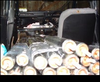
|
|
stu
New Member

Posts: 15
|
Post by stu on Dec 30, 2012 18:59:24 GMT -5
The panels appear to be Wimex VK-180-30 Panels originally supplied by Allied Solar who are one of several possible sources for parts. They are a few years old (some are stamped 2007) and we found them on gumtree.
In preparation for installation of one of these second hand 30 tube "Sydney" type panels, I've had a 250L unvented twin coil solar tank (RM Stelflow) installed - while getting a gas boiler put in. My plumbing is mains fed so no other option I gather but the stainless steel tank which was pricey. There was an opportunity to keep the solar panel, solar tank and boiler very close together (tank and boiler may eventually be enclosed in an insulated cupboard - thanks, Cye!). Meantime around 2" of Armaflex insulation was put on pipework after the photo was taken.
The installation of panel, solar circuit etc will be DIY in early Spring 2013. I am grateful to be drawing again on the knowledge within the co-op e.g. being encouraged to use a 12v pump. and will document / post as much as possible... or as much as seems useful...
I chose to build a storage platform in my loft while I was at it with a strong zone to take the tank which weighs 293 kg wet. This platform usefully floors a section of the loft while ensuring loft insulation underneath is not compressed. The platform was constructed using coach bolts to fix 125x38 mm timbers into all 4 struts of the Fink (or "W" shape) trusses in my roof space (used socket set to driving them into pilot holes made at the neutral axis of each piece of timber where internal forces are zero). I formed some bridging between the bottom chords of 3 trusses for strength under the tank using joist hangers. The last of my inserted beams nearest the gable wall is packed & bolted into the block work. Across this "strong zone" are laid some inch thick boards - stronger than the 8x2 chipboard flooring used elsewhere. There is no measurable deflection. Under the platform I added another 150 mm of quilt insulation bringing the loft insulation (at least under the platform) up to around 450mm as I'll not be underneath there again hopefully.
|
|
stu
New Member
Posts: 15
|
Post by stu on Dec 30, 2012 19:09:11 GMT -5
photo: Stu's tank Attachments:
|
|
|
|
Post by cye on Apr 13, 2013 12:18:13 GMT -5
Well these projects haven't moved on a great deal mainly due to the apalling weather, but we have now managed to divvy up the three lots of tubes and procure some spare 58mm tubes. Nothing installed yet. i transported 60 tubes in the car in two lots of 30, but heard a crack when moving the second lot. the attached pic is the result. you can see the 'mirror silver' (barium) at the base (nipple end) of the vac tube has turned into a milky white, which is what happens when the vacuum is lost and air gets at the barium. the secondhand tubes were bunched into fours and fives bound with clingfilm for transportation. whilst this worked after a fashion, in the light of the breakage i would not recommend it! In hindsight, the correct way to move the secondhand tubes would have been to ask one's friendly neighbourhood commercial solar installer for the correct box and packing - They would be dumping these as a matter of course. The tube goes to the local recycling centre tomorrow. I think the bay for dud flourescent tubes may be the best place to leave it, to ensure safe handling and disposal. More in due course.... Attachments:
|
|
|
|
Post by cye on Jul 12, 2013 6:54:46 GMT -5
As we purchased these panels secondhand, we decided we needed to test as much as possible before we installed the panels on a roof. the following 4 pics show how we pressure test the manifolds using a 22mm stop end at one end of the manifold, and a homemade 15mm air valve at the other. this way we are able to pump air in using a car tyre pump, and check it holds pressure using a car tyre guage this first pic shows the 22mm end stop ready to go on to one end of the manifold. as a compression fitting had been used before on this pipe which may have compressed the pipe and caused possible distortion, we used plenty of PTFE over the olive to increase our chance of getting a good seal. Attachments:
|
|
|
|
Post by cye on Jul 12, 2013 6:55:24 GMT -5
..and another pic, this time of the 'business end' of our homemade pressure test kit. a schrader valve was salvaged from a punctured car tube. These are available free if one asks one's friendly neighbourhood car tyre fitters. the valve and housing are cut from the old tube and glued into a piece of 15mm copper pipe. i used evostick 'nail and seal' which is much better than the name suggests, as it is a MS Polymer sealant which dries to a hard rubber and is virtually indestructable. Another similar adhesive would be the likes of tec7. the sealant was allowed to dry for a few days. the 15mm copper was then fitted to a 22mm->15mm reducer, which then fits to the 22mm pipe on the manifold Attachments:
|
|
|
|
Post by cye on Jul 12, 2013 6:56:07 GMT -5
..and another pic Attachments:
|
|
|
|
Post by cye on Jul 12, 2013 6:56:39 GMT -5
..and another pic. always remember never to overtighten a compression fitting. always tighten it up gently, just a little bit more than hand tight, then check for leaks at a low pressure (say 5psi), then if leaking try another half turn, and so on. the advantage of using air is that we can check for leaks using a mix of washing-up liquid and water brushed over the joints. big leaks cause large bubbles and audible hissing, whereas small leaks cause a 'bunch of grapes' of tiny bubbles to form, becoming visible over 5-10 minutes similar to 'cuckoo spit' (the eggs that froghoppers lay on plants). we made sure we didn't pump more than 2bar (30psi) into the manifold, and then only when we were confident that the compression fittings were fairly solid. i am sure there is a recommended torque setting, but we used this low tech method instead! note that compressing with air can be very dangerous. This is because air, unlike water, is highly compressible and acts like a big spring, i.e., it can store a lot of energy. Think of how an air gun works and then you'll get an idea of how dangerous a sudden release of air could be. should one carelessly overinflate, you could get flying metal, hence care is taken to always keep below 30psi. also, if your compression fittings are very loose, there is small risk they may fly off with the pressure - just make sure no-one is in the line of fire! we had few leaks on our fittings at the start, but then we got the manifold to hold 21psi and this was tested over a period of several hours. as the solar loop is going to be pressurised to 1.5bar (21ish psi) this gives us a good deal of comfort that the manifold is leak-free. (that's Stew in the pic BTW, proudly showing his newly tested manifold) Attachments:
|
|
|
|
Post by cye on Aug 4, 2013 6:16:48 GMT -5
Stu took the manifold home with him that evening to do a longer pressure test. Here's the last update I got from him (he's also emailing Austen because Austen has the same make / model of secondhand panel from the same source) On Tue, Jul 16, 2013 at 5:56 PM, Stewart Lecky <stewartlecky@XXXXXX.XXX> wrote: Cye & Austin My (solar thermal panel) manifold held 25 psi of air - indefinitely! So no leaks.Good news for all 3 I hope. I'm cleaning up the other bits to re-assess what's needed. The black plastic end caps are very greyed with the sun. I'd said to Cye I was going to use Wurth car bumper dye on them,certainly if it gives renewed UV protection. The concern I have is the plastic maybe becoming brittle and fragile over time. There may be no need for me to be worrying about this but I'll but in calls to Allied Solar and Navitron soon about parts, esp. the "top hats" which go at the barium/nipple end of the tubes. Austin, see the Solarco forum where Cye has alreday posted pics of us doing this test. I'll leave the 22mm stop end & Cye's Schroeder valve gadget back so over with him so we can repeat the test. This is where I got my solar tank (full size jpeg file of our 250L one is attached): www.rmcylinders.com/stelflowstandard.htmlI'm sure there are others. Lets get together within a week or a fortnight Austin about a parts order. Stewart |
|
stu
New Member
Posts: 15
|
Post by stu on Nov 10, 2013 16:52:50 GMT -5
Many, many thanks Cye for the enormous help you provided in getting the manifold up on my roof tonight!!!!! This really moves things forward with my thermal installation. I couldn't have tackled that without your effort, confidence and experience. All at quite short notice too. I'll see if I can get the bottom rail up tomorrow and start cleaning and fettling the tubes
|
|
|
|
Post by cye on Nov 11, 2013 18:14:12 GMT -5
Stu, It was a joint effort for sure. Whilst the two of us hoisting a large manifold up onto a roof in the dark was far from best practice and certainly not to be recommended, I won't forget the experience in a hurry! Here's v1 draft of the plumbing schematic I am suggesting. The manifold pipes are 22mm, and we'll connect 15mm to those and use the pipe bender to put a right angle bend in the 15mm pipe to go though the roof. the bender will give a nice smooth curve and, compared with an elbow, will make life easier on the pump and also makes for fewer compression joints (fewer potential leaks!). As soon as the pipework is inside the roof, we'll do the rest in 10mm microbore, except for the leg off to the EV which we'll do in 15mm. Gates and draincocks are all readily available in 15mm and likely to be hard to get in 10mm, plus the standard connections provided in the EV kit will be 15mm too. R1 is a 22mm-15mm straight reducer (all connections are compression type) R2 is a 22-10 reducer (or 28 -10 reducer if the coil is 28mm) R3 is a 15-10 reducer V is a manual air vent, possibly looped back down inside the roof void to save trips onto the roof (yes you can make your vent/bleed pipe like this, provided it rises first to create a high point [to collect air], it can come down again before terminating in a manual bleed valve) T1 is a 22-15 reducing tee with a 10 perpendicular. the 10mm will be used for the vent/bleed pipe T2 is a 10-15-10 tee - we'll use 15mm pipe for the take-off to the EV G is as 15-15 gate valve. DC is a 15-15 in-line drain cock. Together with G, this allows us to drain down the EV to check the air pressure without having to drain the whole solar loop. P is the 12v pump. It pumps on the cold side of the loop, i.e. from the base of the coil out to the panel. EV is the expansion vessel kit such as the Altecnic Robokit, comprising the 12L expansion vessel (EV), a 3 bar pressure relief valve, a filling pipe with double check valve, and the pressure guage. I've just called all this the EV in the schematic for simplicity. I have not yet shown a non-return valve. With the panel being largely at the same height as the hot water tank (latter is in Stu's loft) and with the vac tubes being very good insulators, I don't think we'll have any reverse syphoning at night. Now what have I missed? Attachments:
|
|
stu
New Member
Posts: 15
|
Post by stu on Dec 23, 2013 11:33:36 GMT -5
Nearly all the bits for completion are gathered together now - plumbing fittings, HT insulation, some replacement Al fins, a solar controller, etc. When time and reasonable weather is available the project will be completed. I will continue to take photos as we go and will post something coherent then. S
|
|
|
|
Post by cye on Dec 23, 2013 14:57:38 GMT -5
the bits all 3 of us are short on are the 'nipple protectors' for the base of the vac tubes.
i will take a pic of one and post it up here in the hope that some of the others will have some good ideas. i really don't want to have to turn 90 of these out of nylon in the lathe, there must be a simpler solution lurking somewhere waiting to be discovered!
on a barely related matter, my other half recently bought some glass drinking cups. i spied the words 'borosilicate glass' on the box and naturally my eyes lit up, as this is the same material as vac tubes are made of. the cup spec say it is fit for 500c and will withstand rapid cooling/heating expansion up to 200c, which explains why this material has been used in vac tubes.
|
|


